Why Modeling is Vital
Modeling the landing plume effects is challenging because it is a coupled flow of both gas and granular materials, and sufficient codes have not yet been developed to handle all the physics. A large part of our research has been to understand the physics better so we can support the development of better codes.
Simulations codes are needed to predict the landing plume effects that will occur on various bodies for various landers. We cannot do the correct experiments on Earth to made those predictions because the gravity is wrong, the atmosphere is wrong, and the geology is wrong. We can create simulated atmospheres in giant vacuum chambers, but it is hard to maintain that atmosphere while blowing a large rocket inside he chamber. Also, most owners of expensive vacuum chambers don’t want rockets blowing dust around inside there it can ruin the vacuum pumps. We can do small-scale experiments in vacuum chambers and on reduced gravity aircraft, but it is impossible to consistently solve the scaling equations for granular flow physics, because the size of a sand grains shows up in too many places in the equations, so the only consistent solution is full-scale. Any time you scale down a granular flow problem you are throwing away some of the physics, and if you don’t already completely understand the physics then you can’t be sure if you are throwing away a critical piece. Therefore, we need the experiments to be full-scale.
This leaves us only two options. We can land actual spacecraft on the actual planets and measure what happens, but that is very expensive and risky if we don’t already know what we are doing. Or, we can do computer simulations, but that isn’t possible unless we know how to write the software to get all the physics correct.
Therefore, our team’s strategy has alway been as follows — members of our team have been pursuing this strategy for over 20 years. First, you have to do experiments in every possible situation, including small scale in vacuum chambers and on reduced gravity aircraft, large scale outdoors, and everything else possible. Second, you analyze every possible planetary data set possible to see what is happening in the actual environment. Third, you use all those results to figure out the physics and write the best simulation codes that you can. Fourth, you run computer simulations and compare to all the data sets, and keep creating more data every time you can until eventually you trust the simulations in every possible case. Fifth, you run the simulations to predict what will happen in the lunar or Martian or asteroidal environments, in those cases that you could not actually test on Earth. Sixth, you design missions based on the simulations, and you hope the missions actually go the way the simulations said they would, and if not then you keep making the simulations better.
This strategy puts computer simulations right in the center of importance. Here is an extremely brief review of the available simulation capability and what still needs to be done.
Rarefied and Continuum Flow
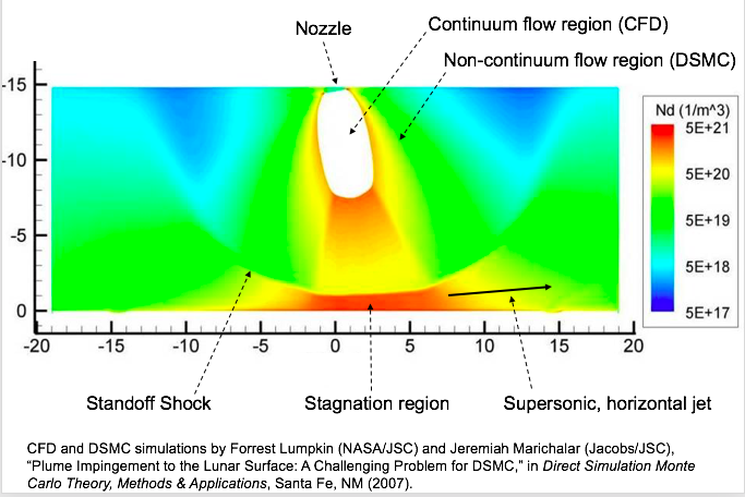
The first problem is the the rocket exhaust is dense and obeys the Navier Stokes equation where it comes out of the rocket nozzle, but a short distance away it has expanded into vacuum so much (it has become rarefied) that it no longer obeys that equation. It becomes transitional and then free molecular flow. This means that different modeling approaches must be applied to different regions of the gas.
More advanced modeling has been developed by companies such as CFD Research Corporation, using equations that two-way couple regions of dense and rarefied flow wherever needed throughout the simulation domain. Typically these more advanced codes do not yet have turbulence models, because the coupling of turbulence through the rarefied regions requires more work to figure out the physics. Without turbulence, they may not yet be completely accurate in determining how the regolith grains will be eroded. However, progress is being made.
Coupled Gas and Granular Flow
The next problem is to couple the flow of the gas to the flow of the regolith grains after they have been lifted from the surface (as in the Viscous Erosion regime). The simplest method to do this is to use one-way coupling, where the gas equations are solved first and from them you calculate the forces on the grains to determine where the grains will go. This is not a great method because in reality as the grains speed up by taking momentum from the gas, then the gas should slow down. That requires two-way coupling, to solve both the gas and grains at the same time. By not letting the gas slow down, it predicts the grains will go faster than they really do — but by how much? It might be an OK approximation, but maybe not…or maybe not in all situations.
Another issue is that the grains will collide with each other while they are flying along, and research shows that this is important to include in simulations to get accurate results (Anand et al., 2013; Berger et al., 2015). Small grains will speed up faster than the big ones do, so they should run into the big ones and that transfers momentum from smaller grains to larger ones. But again, it might be an OK approximation to ignore this…or maybe not.
The Simplest Simulation
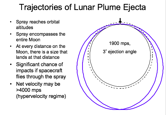
To start out, we have performed the simplest case of coupled gas-granular flow by using only one-way coupling to the grains and ignoring particle collisions, tracking only one particle at a time (Lane et al., 2008, 2010). The results show that particles will travel all the way around the Moon for a Lunar Module sized lander and some particle escape all the way off the Moon into solar orbit. We partially validated this method by showing that it predicts the correct ejection angle of particles (compared to what we can measure in the Apollo landing videos) and the correct velocities for ejected rocks. We cannot verify the velocities of the smaller particles from those videos, so more work is needed. Combining this with an equation of erosion rate, we summed up all the trajectories during a lunar landing and predicted how much total material goes where.
Two-Way Coupling with Particle Collisions
Our team member David Goldstein has worked with doctoral student Aaron Morris to perform Direct Simulation Monte Carlo (DSMC) simulations where the gas and grains are two-way coupled and the grains can collide with each other. Simulation of rocket plume impingement on the lunar surface is complicated – the gas and dust flows involve rarefied/continuum transition, compressibility, gas mixtures, two-phase flow and gas-surface interaction – such physical effects best modeled by direct numerical simulation. Members of our team have analyzed the problem of plume impingement as a rocket takes off from or lands on the lunar surface. The plume effects were parametrically examined with an established Navier-Stokes (NS) equation solver in the near field. The direct simulation Monte Carlo (DSMC) method used the (unsteady) NS output along a suitable boundary to model the surrounding rarefied atmosphere. Our long-range goal is to develop a comprehensive understanding of where the plume gas and dust go during and after rocket operations near the lunar surface. In the short term we have begun to bridge the hydrodynamic and free molecular regimes in modeling of flows of gas and dust and have created a firm computational model applicable to a range of design problems.
Results
Then-graduate student Aaron Morris presented a unique and substantial examination of several aspects of the problem (see this link). Some highlights are presented below.
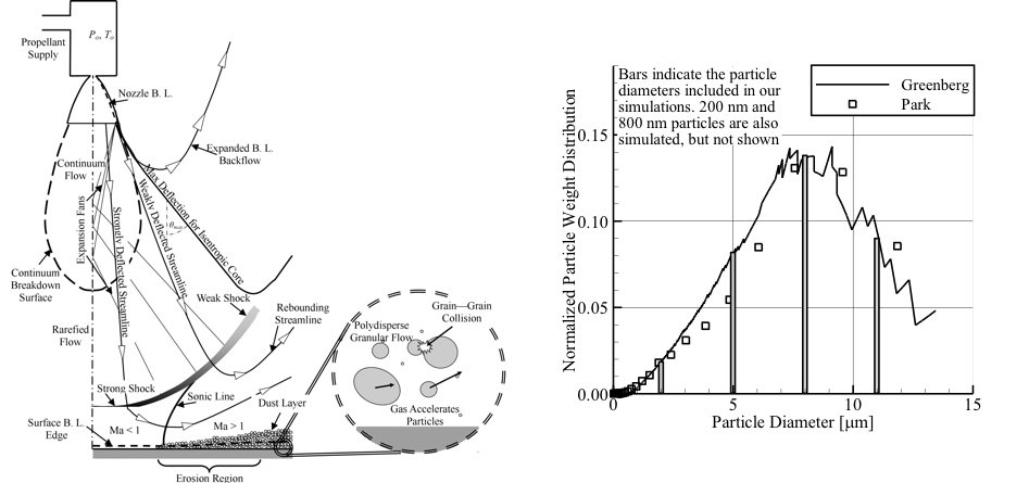
The first figure illustrates the complicated physics occurring in the near field of a rocket plume impinging on the lunar surface. We have now simulated all of these phenomena, including grain-grain inelastic collisions, grain thermal properties, grain scouring off the surface, grain size distributions based on Apollo samples (fig. 1b), and grain radiative cooling (all new to the DSMC method) and created an end-to-end physical model. Continuum plumes that expand into vacuum will eventually undergo continuum breakdown and transition towards free molecular flow. Internal and directional temperatures are the first properties to exhibit departures from equilibrium. Breakdown occurs because collisions are no longer able to equilibrate the directional translational temperatures and internal energy modes in a sufficiently rapid manner. (Morris et al., 2010a)
We start with a continuum DPLR simulation of the plume in the near field of an engine based on the Apollo lander main engine whose properties are given below. (DPLR is a NASA code often used to simulate continuum hypersonic flow fields).
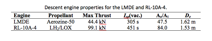
The Lunar Module Descent Engine (LMDE) burned a 1:1 mixture (by volume) of Aerozine-50 (hydrazine and unsymmetrical dimethylhydrazine) and used nitrogen tetroxide as the oxidizer. Figure 2 illustrates one such solution we obtain with a modified chemical composition. In Figure 2(b) we illustrate the hybrid solution obtained with DPLR in the near field and DSMC further out for an engine hovering well above ground level so no interaction of the plume with the surface occurs. These are the best extant simulations of similar rockets exhausting into vacuum. (Morris et al., 2015a)
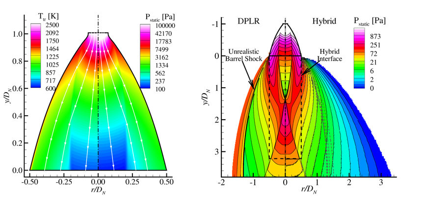

Figure 3 illustrates the reflection of the plume off of the lunar surface when the engine is hovering at 5m altitude and when it drops down to 2 m. There is a huge change in flow character. We have examined boundary layer profiles, heat fluxes, shear stresses, etc., due to the gas flow out of the nozzle. We use the gas dynamic pressure a small distance above the surface (see fig 4b) to compute the regolith erosion rate and have compared that in detail to previous (Roberts) theory. We have parametrically examined erosion profiles for different classes of regolith grain sizes as a function of vehicle height (Fig. 4) and integrated an Apollo-like landing sequence to obtain predicted crater depths. (Morris et al., 2015a)

From a practical point of view, perhaps the most important issue is where and how fast different classes of grains go. Figure 5 illustrates a comparison between the speed distributions of different sized grains in the near field. We have examined whether grains melt, whether their coupling to the gas flow is important (it is and we fully simulate it), and whether grain-grain collisions are important (they are and we simulate those too). Coupling the grain mass loading to the gas flow substantially slows the gas flow and changes the scouring rate by a factor of two. Grain-grain collisions scatter grains, especially the smaller ones, high up out of the main dust sheet which forms near the ground. See Fig. 5. (Morris et al., 2012a; Morris et al., 2015a)

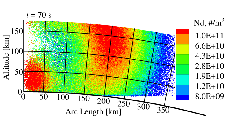
We have examined how grains and gas disperse out into the very far field over many minutes. Figure 6 illustrates this for two different grain sizes. Note that the axes are now in kilometers.

Perhaps most interesting from that landing sequence result is the presence of two classes of gas clouds that occur. There is the gas which simply rapidly blows away and the gas which gets slowed by its intimate interaction with the massive dust cloud before it too can escape. This process is illustrated in figure 7. (Morris et al., 2012a)
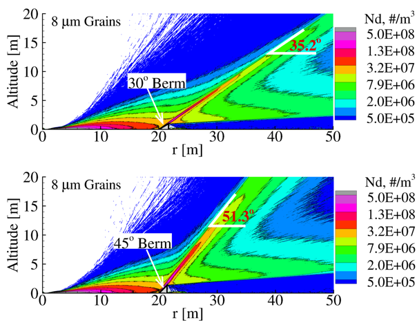
One can consider placing a barrier around a landing site to deflect the dust plumes from nearby structures. We have parametrically examined the effects of such barriers at different distances from the landing site, of different heights, angles and restitution coefficients. Figure 8 illustrates one such comparison. (Morris, 2013)
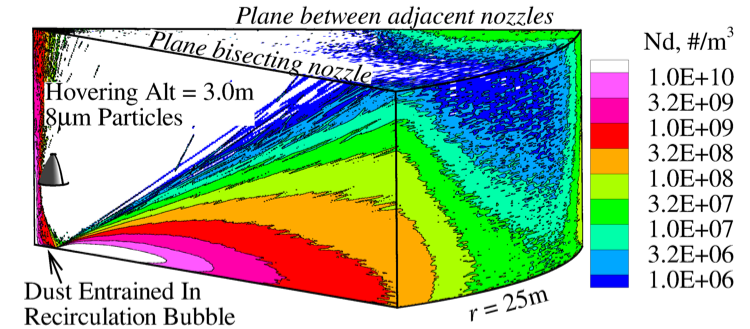
Finally, we have examined the effect of having multiple nozzles on a lander. The flows are very different than those when there is a single engine, mostly because of the shock-shock interactions which occur. There can be substantial asymmetry and directional jetting of the dust flows. Figure 9 shows an example of the 3D flow field. (Morris et al., 2015b)
Granular Boltzmann Method
A new method was developed by CFD Research Corporation using the Granular Boltzmann Equation by Garzo, Hrenya and Dufty (GHD theory). This method does not actually calculate the trillions of particle individually, but rather it treats each size range of particles as a continuum fluid based on the Granular Boltzmann Equation. The 2012 paper by Murray, Benyahia, Metzger, and Hrenya shows that only 9 discrete particle sizes need to be considered as separate fluids in order to accurately predict the flow of the entire size distribution of particles. Thus, the gas is the 10th fluid, and this mixture of 10 “fluids” can be treated using an Eulerian-eulerian framework to solve the entire problem. Unfortunately, it is extremely time-consuming even on a supercomputer so it is not practical. We are currently working with CFD Research Corporation on a method to adapt this modeling using reduce-order interpolations.
Next: ISRU for Mitigating Plume Effects
Back: Geological Considerations for Landing Plume Effects
<< Return to Main Page
References
- Anand, A., K.J. Berger, P.T. Metzger, and C.M Hrenya (2013), “Role of Collisions in Erosion of Regolith during a Lunar Landing,” Physical Review E87, 022205 (2013).
- Berger, K.J., A. Anand, P.T. Metzger, and C.M. Hrenya, (2015), “Erratum: Role of collisions in erosion of regolith during a lunar landing (vol 87, 022205, 2013)”, Physical Review E91(1), 1-1 (2015).
- Lane, J.E., P.T. Metzger, and C.D. Immer (2008), “Lagrangian trajectory modeling of lunar dust particles,” Proceedings of Earth and Space 2008, 11th Biennial ASCE Aerospace Division International Conference on Engineering, Construction and Operations in Challenging Environments, Long Beach, California, Mar. 3-5, 2008.
- Lane, J. E., P.T. Metzger, and J.W. Carlson (2010), “Lunar Dust Particles Blown By Lander Engine Exhaust in Rarefied and Compressible Flow,” Proceedings of Earth and Space 2010, 12th Biennial ASCE Aerospace Division International Conference on Engineering, Construction and Operations in Challenging Environments, Honolulu, HI, Mar. 14-17, 2010.
- Morris, A., Varghese, P., Goldstein, D. (2010a) “Plume Impingement on a Dusty Lunar Surface”. Rarefied Gas Dynamics, 27thInternational Symposium on Rarefied Gas Dynamics, 2010, Pacific Grove, CA, July 2010. Ed. D. Levin, I. Wysong & A. Garcia, AIP Vol. 1333.
- Morris, A, Goldstein, D., Varghese, P., and Trafton, L. (2012a), “Far field deposition of scoured regolith resulting from lunar landings,” Rarefied Gas Dynamics, 28thInternational Symposium on Rarefied Gas Dynamics, 1501, pp. 1220-1227, 2012, Zaragosa, Spain.
- Aaron Morris’ dissertation, “Simulation of Rocket Plume Impingement and Dust Dispersal on the Lunar Surface”, Spring, 2013. (see pdf available here)
- Morris, A., Varghese, P., Goldstein, D. (2011a) “Monte Carlo Solution of the Boltzmann Equation Via a Discrete Velocity Model.” Computational Physics 230, #4, Feb. 2011.
- B. Morris, D. B. Goldstein, P. L. Varghese, L. M. Trafton (2015a), “Approach for Modeling Rocket Plume Impingement and Dust Dispersal on the Moon,’’ J. Spacecraft and Rockets, vol. 52, No. 2, (2015) pp. 362-374, doi: 10.2514/1.A33058.
- B. Morris, D. B. Goldstein, P. L. Varghese, L. M. Trafton (2015b), “Lunar dust transport and scouring resulting from single and four-engine plume impingement,” AIAA Journal, http://dx.doi.org/10.2514/1.J054532, Dec. 2015.
- Morris, A. B., Goldstein, D. B., Varghese, P. L., Trafton, L. M. (2012b), “Modeling the Interaction between a Rocket Plume, Scoured Regolith, and a Plume Deflection Fence”, Earth and Space, 13th ASCE Aerospace Division Conference on Engineering, Science, Construction, and Operations in Challenging Environments, and the 5th NASA/ASCE Workshop On Granular Materials in Space Exploration, Pasadena, CA, April 15-18, 2012, pp. 189-198.
- Goldstein, D., Varghese, P., Trafton, L., Moore, C., Stewart, B., Walker, A., McDoniel, W., Yeoh, S., Morris, A., Summy, D., Kizer, J. (2009), “Rarefied Atmospheric Flow,” Invited Talk, University of Texas Planetary Science Symposium, Oct. 2, 2009.
- Morris, A., Goldstein, D., Varghese, P. and Trafton, L. (2011b), “Modeling a dusty plume impinging on the lunar surface,” Invited Talk given by Morris at the Workshop on Lunar/Martian Plume Effects, Cape Canaveral, Jan. 21, 2011.
- Morris, A., Goldstein, D., Varghese, P., and Trafton, L. (2011c), “Simulation of a rocket plume entraining lunar dust,” presented by Morris at DSMC11, DSMC workshop, Sante Fe, NM, Sept. 2011.
- Morris, A., Goldstein, D., Varghese, P., Trafton, L. (2012c), “Simulation of Rocket Plume Impingement and Dust Dispersal on the Lunar Surface,” Invited Talk presented by Morris at The University of Colorado, November 17, 2012.
- Murray, J. A., S. Benyahia , P. Metzger, and C. M. Hrenya (2012), “Continuum Representation of a Continuous Size Distribution of Particles engaged in Rapid Granular Flow,” Physics of Fluids 24, 083303 (2012).
Next: ISRU for Mitigating Plume Effects
Back: Geological Considerations for Landing Plume Effects
<< Return to Main Page